Isometric Pipe Drawing Symbols
Isometric Pipe Drawing Symbols - Knowing legends and symbols that are universal for reading a piping isometric drawing is much helpful to gain info about the piping material or piping fittings that are going to be used for fabrication or construction work. In cad drawing, only x and. All of our vector cad models are of the highest quality. The drawing axes of the isometrics intersect at an angle of 60°. Correct skey is not configured in isoskeyacadblockmap.xml. In piping isometric drawings, dimensions are typically indicated using notes, labels, or numbers placed against the corresponding components.these dimensions represent the length, diameter, and other specifications. Project specific instructions for isometrics checking. A piping isometric drawing is a 2d drawing in which piping is represented like a 3d drawing. Web contains 1,120 isometric piping symbols in.dwg format. Web understanding piping isometric drawings: Web a piping isometric drawing is a technical drawing that depicts a pipe spool or a complete pipeline using an isometric representation. All of our vector cad models are of the highest quality. Open the autocad plant 3d project drawing file. Select the pipe and check its content iso. Web faqs on piping isometric drawings q. Web know and identify pipe fitting symbols on your piping isometrics (flanges, reductions, caps, spool pieces, unions…) know and identify the piping isometric symbols of safety devices that are used to safely isolate, vent & drain process equipment for ease of maintenance (spectacle and spade blinds, double block, and bleed valves…) Web what is a piping isometric? The layouts must comply with safety codes, government Web piping and instrument diagram (p&id): In piping isometric drawings, dimensions are typically indicated using notes, labels, or numbers placed against the corresponding components.these dimensions represent the length, diameter, and other specifications. Knowledge of symbolic representation of piping is helpful to gain quick knowledge. Web know and identify pipe fitting symbols on your piping isometrics (flanges, reductions, caps, spool pieces, unions…) know and identify the piping isometric symbols of safety devices that are used to safely isolate, vent & drain process equipment for ease of maintenance (spectacle and spade blinds, double block,. Web isometric is not extracted correctly for custom created pipe sizes in autocad plant 3d. Piping layouts and sectional drawings: How are dimensions represented in piping isometric drawings? Web piping and instrument diagram (p&id): The drawing axes of the isometrics intersect at an angle of 60°. From this drawing, we will get information like line number, line size, insulation, fluid commodity, special notes (like no pocket, requirement of spectacle blind in equipment nozzles, pressure head, specific straight length requirement for instrument connections), etc. Web isometric drawing symbols for valves. They are used to outline the structure in the space of a piping system. Web the symbols. Web a piping isometric drawing is a technical drawing that depicts a pipe spool or a complete pipeline using an isometric representation. A piping isometric drawing is a 2d drawing in which piping is represented like a 3d drawing. Web know and identify pipe fitting symbols on your piping isometrics (flanges, reductions, caps, spool pieces, unions…) know and identify the. It is the most important deliverable of piping engineering department. Open the autocad plant 3d project drawing file. Web piping isometric drawing symbols for various markings. In cad drawing, only x and. Piping fabrication work is based on isometric drawings. In cad drawing, only x and. Web piping isometric drawing is an isometric representation of single pipe line in a plant. Web contains 1,120 isometric piping symbols in.dwg format. Fitting symbols and orientation for the orientation of the fittings and valves, it is recommended they are drawn parallel to the last change in direction or branching in the pipeline, as. A piping isometric drawing is a 2d drawing in which piping is represented like a 3d drawing. Web understanding piping isometric drawings: Web a piping isometric drawing is a technical drawing that depicts a pipe spool or a complete pipeline using an isometric representation. Symbols and abbreviations should be interpreted according to the standard piping codes used in the drawing,. Web piping isometric drawing is an isometric representation of single pipe line in a plant. Mechanical symbols for isometric drawings. Web understanding piping isometric drawings: Fitting symbols and orientation for the orientation of the fittings and valves, it is recommended they are drawn parallel to the last change in direction or branching in the pipeline, as shown in the image. Select the pipe and check its content iso. Mechanical symbols for isometric drawings. This comprehensive block library (.dwg files) organizes all of the symbols for easy and instant access. The layouts must comply with safety codes, government Web isometric is not extracted correctly for custom created pipe sizes in autocad plant 3d. In piping isometric drawings, dimensions are typically indicated using notes, labels, or numbers placed against the corresponding components.these dimensions represent the length, diameter, and other specifications. Symbols and abbreviations should be interpreted according to the standard piping codes used in the drawing, such as ansi/asme. How are dimensions represented in piping isometric drawings? Knowing the piping drawing symbols will provide. Project specific instructions for isometrics checking. In this dwg file you will find a huge collection of pipeline isometric drawings which are created in 2d format. Web isometric drawing piping symbols roy a. Web piping and instrument diagram (p&id): Checkout list of such symbols given below. Web a piping isometric drawing is a technical drawing that depicts a pipe spool or a complete pipeline using an isometric representation. In piping isometric drawings, dimensions are typically indicated using notes, labels, or numbers placed against the corresponding components.these dimensions represent the length, diameter, and other specifications. Web isometric drawing symbols for valves. Drawing symbols, callouts, coordinates, and elevations provide detailed information of the pipe’s configuration and routing as it travels through the facility. Knowing the piping drawing symbols will provide various. Web various symbols are used to indicate piping components, instrumentation, equipments in engineering drawings such as piping and instrumentation diagram (p&id), isometric drawings, plot plan, equipment layout, welding drawings etc. It is the most important deliverable of piping engineering department. In cad drawing, only x and. Knowledge of symbolic representation of piping is helpful to gain quick knowledge. Web what is a piping isometric? The drawing axes of the isometrics intersect at an angle of 60°.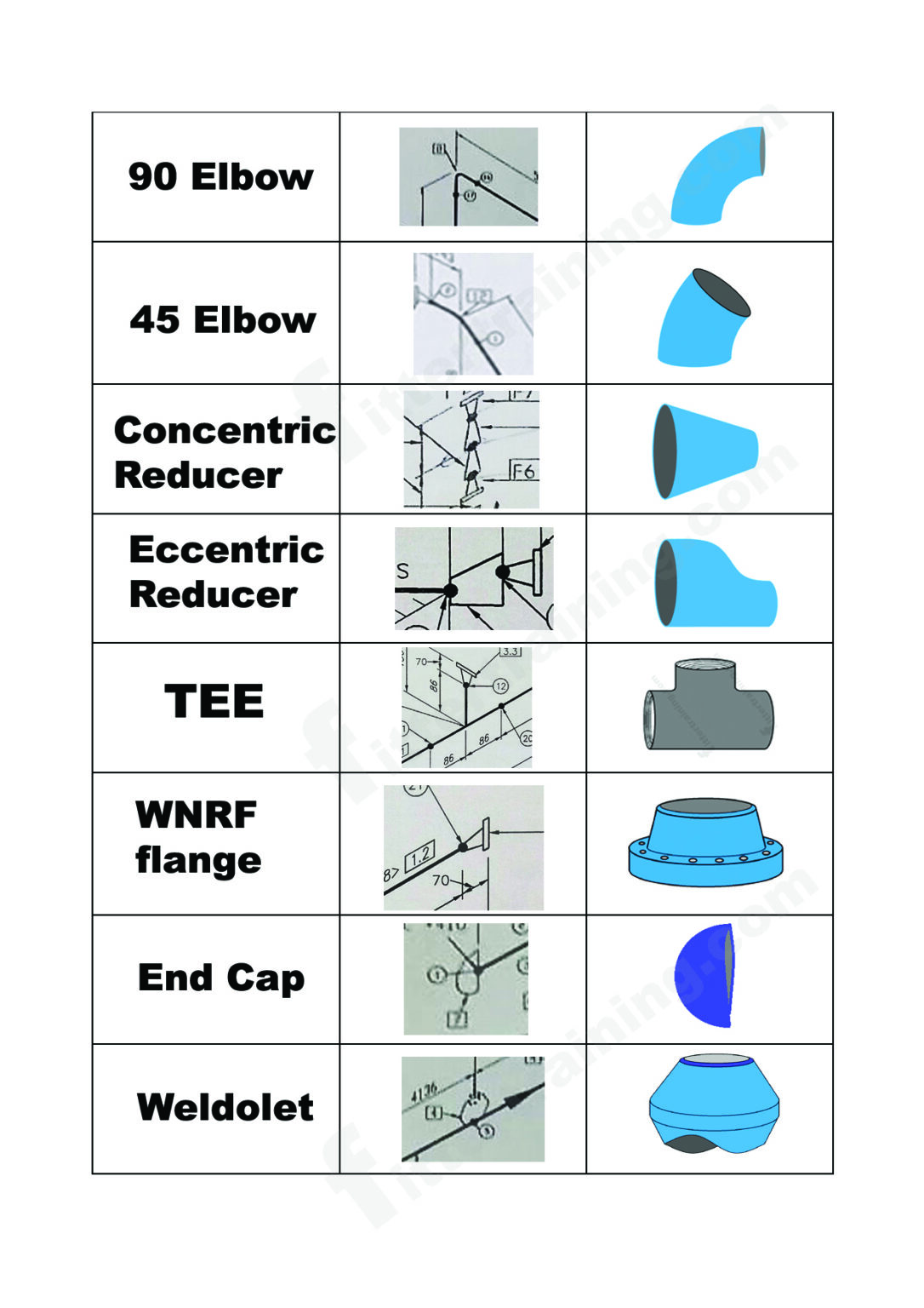
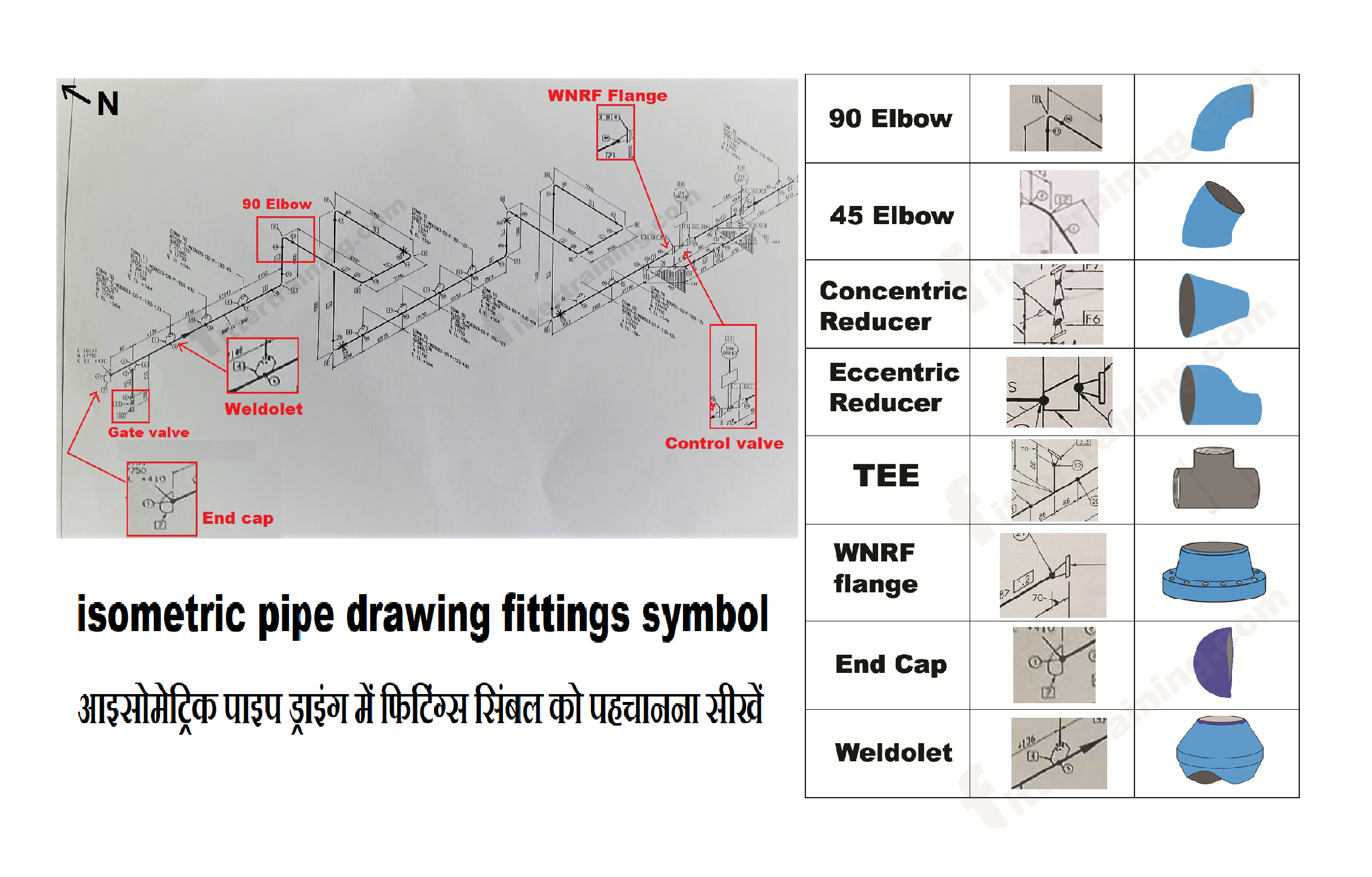
isometric pipe drawing fittings symbol Fitter training
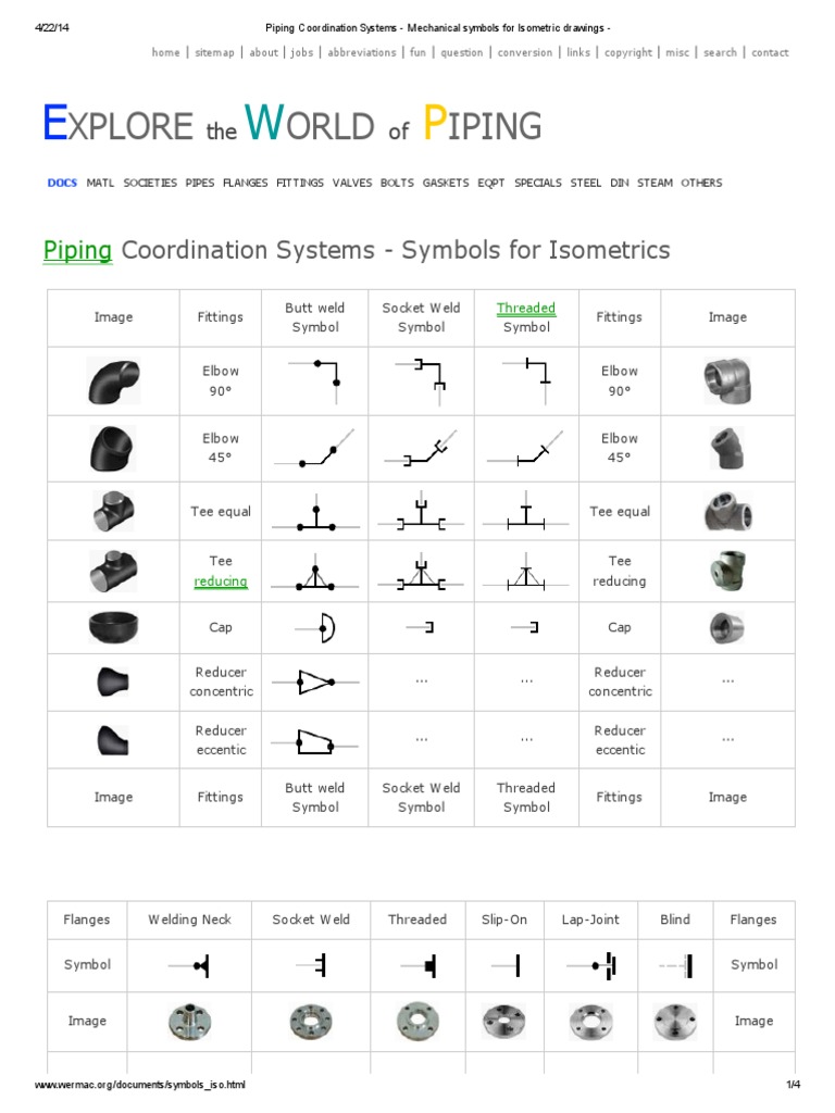
Piping Coordination System Mechanical symbols for Isometric drawings
How To Use A Ridgid Pipe Threading Machine Piping Symbols For

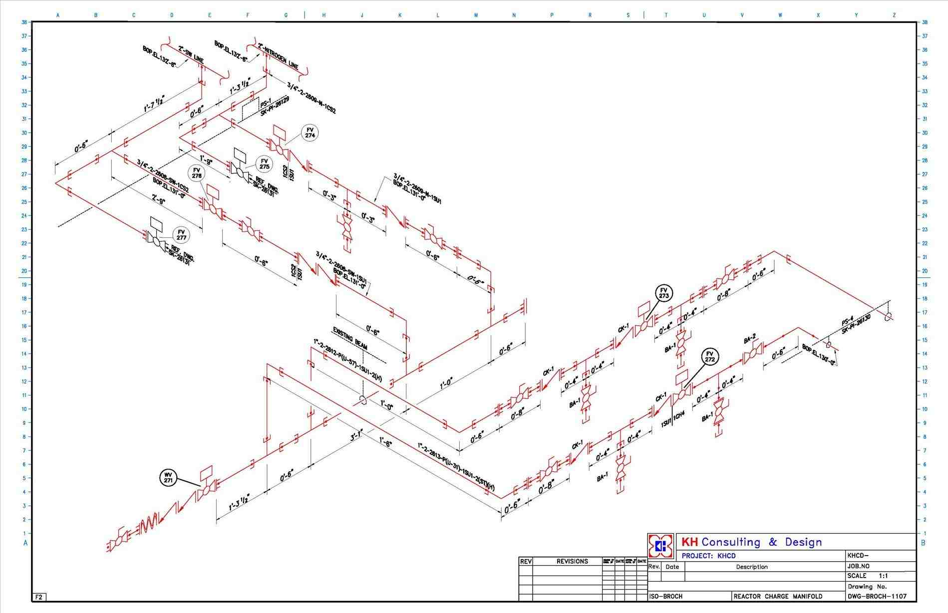
What is Piping Isometric drawing? How to Read Piping Drawing? ALL

Piping Isometric Drawings The Piping Engineering World
Isometric Pipe Drawing Symbols

How to read isometric drawing piping dadver

Piping Isometric Drawing Symbols Pdf at Explore
Piping Coordination Systems Mechanical symbols for Isometric drawings

Piping Isometric DWG Symbols Free Download Drawing in CAD
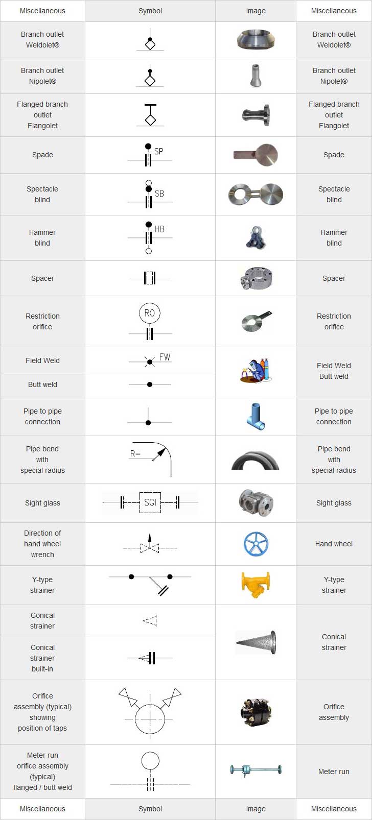
Web Piping Isometric Drawing Symbols For Various Markings.
Understanding The Intricacies Of Pipeline Isometric Drawings, Including Iso Standard Isometric Symbols, Fittings, Flanges, Valves, And Special Components, Is Foundational For Professionals In The.
Parisher Pipe Drafting And Design Roy A.
Web Isometric Drawing Symbols For Piping Fittings.
Related Post: